

3D Welding Workbench Installation And Debugging Instructions
Nov 24, 2025
Leave a message
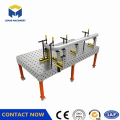
3D Welding Workbench Installation and Debugging Instructions
I. Pre-Installation Preparation
* **Site Selection**
Install on a flat, firm, and dry surface to avoid unevenness that could cause shaking and affect welding accuracy and stability.
Leave 1.5-2 meters of operating space around the workbench, away from large machinery and vibration sources, and ensure good ventilation to remove harmful gases.
* **Platform Cleaning and Inspection**
Thoroughly clean the work surface with a dedicated cleaning agent to remove dust, oil, and other impurities.
Inspect the surface for scratches, dents, or deformation. Check the positioning holes and T-slots for integrity and repair any problems immediately.
* **Tools and Fixtures Preparation**
Prepare welding machines, welding torches, welding rods, and other tools according to the shape and size of the workpiece, ensuring they are in good working order.
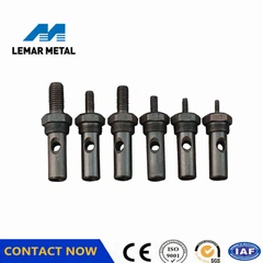
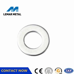
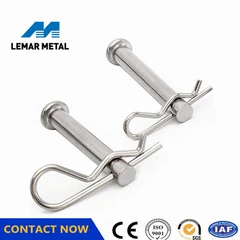
Select fixtures (such as quick clamps and locating pins) that match the platform's positioning holes and T-slots, and check that all components are complete and flexible.
II. Installation Steps
* **Platform Assembly**
If it is a modular structure, connect the components sequentially according to the instructions, using dedicated bolts and nuts to secure them, ensuring the platform is firmly assembled and level.
**Workpiece Positioning**
Place the workpiece on the platform and perform initial positioning using positioning holes, T-slots, positioning pins, and positioning blocks.
Use measuring tools such as calipers and dial indicators to adjust the position, ensuring the positioning accuracy meets requirements.
**Fixture Installation and Clamping**
Install the fixture and clamp the workpiece, ensuring it remains stable and does not move during welding.
**III. Debugging and Calibration**
**Accuracy Calibration**
Use a level to check flatness (≤0.10/1000mm) and perpendicularity (≤0.10/200mm). Control the height difference at the four corners by adjusting the support screws.
Use a coordinate measuring machine to check the hole spacing error (e.g., D28 series requires ±0.05mm). Repeatedly clamp and test the repeatability of the positioning pins (deviation ≤0.01mm).
**Dynamic Performance Testing**
After loading the rated weight (e.g., 2 tons), check the change in flatness; the deformation must be ≤0.02mm.
When linked with the robotic arm, verify the deviation between the welding path and the theoretical trajectory using a laser tracker.
IV. Precautions for Use
Operating Procedures
Avoid placing the workpiece on the worktable for extended periods. Ensure the support points are aligned with the main support points to prevent localized deformation due to pressure.
Monitor the weld seam tracking in real-time during welding. Pause and adjust immediately if any abnormalities are detected.
Maintenance and Care
Clean the surface of weld slag and dust after each use. Apply anti-rust oil and cover with a protective film if the workpiece is not in use for an extended period.
Retest key parameters every 6 months and record data trends to predict accuracy degradation.
Environmental Control
Maintain a stable ambient temperature (20±5℃) and humidity ≤60% to prevent thermal deformation from affecting accuracy.
V. Common Problem Handling
Accuracy Degradation: Immediately recalibrate. Check if the support screws are loose or if the ambient temperature and humidity are abnormal.
Loose Fixtures: Check the torque of the connecting bolts to ensure sufficient clamping force.
Equipment Malfunction: Contact a professional organization for factory repair (e.g., high-precision platforms should be scraped every 2 years).
Feel free to contact me for more details!↓↓↓
Cell:+8615995269947(Whatsapp/Wechat)
Email:Evasummer@lemarmetal.com
www.lemarmachine.com
Send Inquiry