

How to Inspect the Accuracy of a 3D Welding Table After Heat Treatment Deformation
Jun 08, 2026
Leave a message
Step 1: Prepare the Inspection Reference
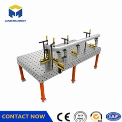
Place the welding table on a standard inspection platform. Adjust the support pads to level the table roughly, ensuring it remains stable and wobble-free throughout the inspection process.
Step 2: Inspect Key Accuracy Parameters by Category
1. Flatness Inspection (Critical parameter; relates to warping/distortion)
Standard precision requirements: Use a frame-type spirit level and feeler gauges. Select measurement points at 500mm intervals along the X and Y axes. Record the gap between each point and the reference platform; the maximum gap value represents the maximum surface deformation.
High-precision requirements: Use a laser flatness tester or 3D profile scanner to scan the entire table surface. Generate a complete surface deviation map and automatically output maximum and minimum deformation values for greater data accuracy.
2. Hole Pattern Positioning Accuracy Inspection (Relates to hole position distortion)
Use a high-precision vernier caliper or Coordinate Measuring Machine (CMM). Randomly select multiple sets of adjacent and diagonally opposed positioning holes. Measure the change in center-to-center distance before and after heat treatment, and compare the results against factory tolerance specifications to determine if deformation exceeds limits.
3. Perpendicularity/Parallelism Inspection (Relates to overall twisting or bending distortion)
Perpendicularity: Place a square against the side and top surfaces of the welding table. Use feeler gauges to measure the gap between the square and the working surface to determine the perpendicularity deviation.
Parallelism/Twisting Distortion: Stretch a standard steel wire tightly between two diagonally opposite corners of the table. Measure the gap differences between the wire and various points on the table surface; larger differences indicate more severe twisting distortion.
Step 3: Compliance Determination
Compare the measurement results with factory accuracy standards:
If all parameters fall within tolerance limits (flatness ≤ 0.05mm/1000mm; hole center distance deviation ≤ ±0.05mm), the deformation does not affect usability;
If a single parameter slightly exceeds tolerance, it is classified as correctable deformation;
If multiple parameters significantly exceed tolerance, the deformation is excessive, and correction is not cost-effective.

Send Inquiry