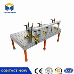


What are some common causes of positioning deviations in 3D welding tables?
May 06, 2026
Leave a message
1. Worn or enlarged positioning holes:
Frequent insertion and removal of PC pins or inadequate cleaning over a long period can lead to wear on the inner walls of the positioning holes, increasing the clearance.
This manifests as loose PC pin insertion and excessive rotational runout (>±0.02mm), affecting workpiece positioning consistency.
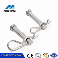
2. Deformed or worn PC pins:
Improper force during use or improper storage can cause PC pins to bend, scratch, or deform at the ends.
Deformed PC pins cannot accurately fit into the holes, causing systemic misalignment.
3. Table surface flatness deviation:
The table surface may experience localized depressions or bulges due to external impact, overload, or thermal deformation, with flatness exceeding 0.08mm/m².
This affects the flatness of module splicing, causing "suspended" or "warped" surfaces, compromising the overall reference datum. 4. Damage to the reference surface of the fixture module
Scratches, dents, or corrosion appear on the mating surfaces of standard modules such as squares and square boxes, resulting in joint gaps >0.03mm.
Accumulated errors between modules are transmitted to the workpiece, causing final assembly deviations.
5. Failure to perform periodic calibration
If calibration is not performed for more than 3–6 months, minor deformations and wear accumulate into significant errors.
Especially in workshops with high-frequency use or large environmental fluctuations, accuracy drift is faster.
6. External environmental interference
Excessive temperature differences (>10℃) cause thermal expansion and contraction, affecting the stability of hole spacing;
Strong vibration sources (such as stamping equipment) cause structural loosening, reducing the reliability of repeatability positioning.

Send Inquiry