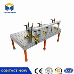


How to solve the positioning deviation of 3D welding table
May 04, 2026
Leave a message
1. Perform Accuracy Calibration Immediately
Use a coordinate measuring machine (CMM) or laser tracker to check the flatness of the table surface (standard ≤0.08mm/m²) and the positional accuracy of the positioning holes (runout ≤±0.02mm).
Compensate for out-of-tolerance areas; if necessary, return the reference surface to the factory for repair.
After calibration, verify the consistency of repeatable positioning using standard workpieces to ensure the deviation is restored to within ±0.1mm.
2. Inspect and Replace Worn Parts
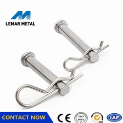
Positioning Holes and PC Pins: If the PC pins are loose or have excessive runout, check if the hole walls have been worn and enlarged due to long-term use. Minor wear can be replaced with thickened PC pins; severe wear requires platform rework.
T-Slots and Slider: Check the slot opening for burrs, deformation, or debris. Clean and trim with a special scraper to ensure smooth, unobstructed slider operation.
Module Reference Surfaces: If the mating surfaces of standard parts such as angle rulers and square boxes are scratched or deformed, they should be sent for repair or replacement.
3. Standardize operating procedures to avoid human-caused damage.
Do not use hammers, pry bars, or other forceful methods to install workpieces or fixtures, as this may damage the positioning structure.
Tighten symmetrically during clamping to avoid unilateral force that could cause slight deformation of the table surface.
Clean away metal shavings and welding slag promptly after each use to prevent impurities from embedding in the slots and creating a "lifting" effect.
4. Troubleshoot intelligent system errors (applicable to integrated vision-guided platforms).
If equipped with a 3D vision or laser-guided system, perform eye-to-hand calibration to unify the coordinate systems of the sensors and robotic arm.
Check for sensor lens contamination and optical path misalignment. Recalibrate and verify the accuracy of the welding torch path.
Ensure the control system has been loaded with the latest calibration parameters to avoid dynamic deviations due to parameter loss.
5. Optimize the operating environment and load management.
Maintain constant temperature and humidity (20±2℃, humidity 40–60%) to reduce the effects of thermal expansion and contraction.
Avoid localized overloading or prolonged concentrated loading; ensure even weight distribution of the workpiece to prevent localized table surface depressions.
Keep away from high-vibration equipment such as stamping and forging machines to prevent structural loosening.

Send Inquiry