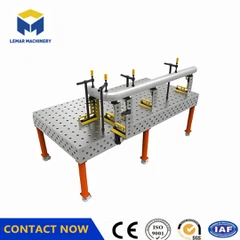
How to correct the positioning deviation of a 3D welding table
May 15, 2026
Leave a message
1. Perform Professional Precision Calibration
Use a coordinate measuring machine (CMM) or laser tracker to perform gridded sampling (50mm x 50mm) on the table surface, checking flatness (standard ≤ 0.08mm/m²) and positioning hole accuracy.
For out-of-tolerance areas, restore the reference surface through grinding, compensation shims, or CNC dressing; after calibration, update the control system compensation parameters to achieve dynamic correction.
2. Replace or Repair Critically Worn Components
Positioning Hole Treatment: Minor hole enlargement can be temporarily addressed by replacing with thickened PC pins; severe wear requires return to the factory for grinding repair or module replacement.
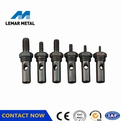
PC Pin Replacement: Check the straightness and diameter of PC pins; replace immediately if bending or scratches are found, ensuring a fit runout ≤ ±0.02mm.
Module Reference Surface Repair: When the mating surfaces of standard parts such as angle rulers and square boxes are damaged, grind to a flatness ≤ 0.03mm or replace with new parts.
3. Standardize operating procedures and eliminate human error.
Do not hammer or pry the installed workpiece to prevent mechanical damage to the T-slots and positioning holes.
Tighten symmetrically during clamping to avoid unilateral force causing slight deformation of the worktable.
Remove iron filings and welding slag after each use to prevent impurities from embedding and creating a "lifting" effect.
4. Optimize environment and load management.
Maintain a constant workshop temperature (20±2℃) and low vibration to reduce the impact of thermal expansion and contraction and structural loosening.
Distribute workpiece weight evenly to avoid localized overload (>10 tons/㎡) that could cause worktable sagging.
Keep away from strong vibration sources such as stamping and forging presses; install vibration-damping foundations if necessary.
5. Integrate intelligent closed-loop compensation system.
If equipped with a 3D vision or laser guidance system, perform eye-to-hand calibration to unify the coordinate system of the sensors and robotic arm.
Enable online detection to identify minute deviations in real time and automatically adjust the welding torch path to achieve closed-loop control.
✅ Recommendation: After calibration, use standard workpieces to perform ≥5 repeated clamping tests to verify whether the deviation is stable within ±0.1mm, and establish a monthly sampling inspection mechanism to provide early warning of drift trends.

Send Inquiry